|
|
||
|
|
|
|
|
|
|
|
||
|
|
|||
| |||||||||||||
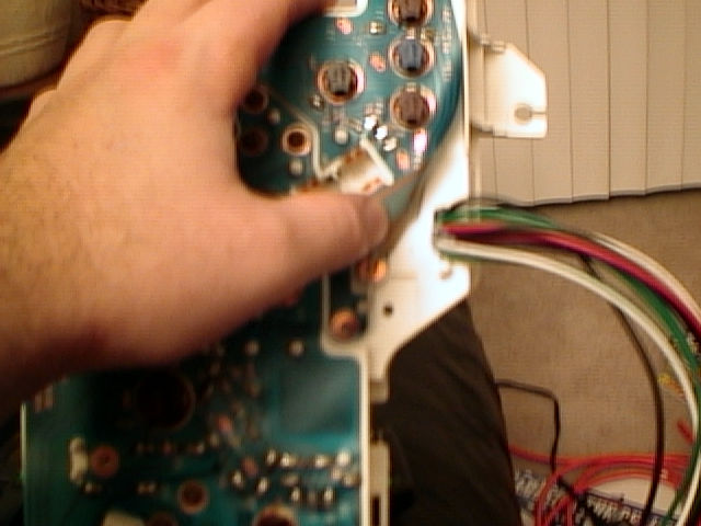
SPA In-Dash Gauge InstallHere is some information about replacing the stock water temp and oil pressure gauges with some SPA dual digital gauges. The project is still in progress, but I am getting close to completion. Gauge Selection and Sensor SetupI wanted a fuel pressure gauge and the stock water temp gauge is highly non-linear, meaning it isn't really that honest about the real water temps. So, I got an SPA dual digital gauge with both Fuel Pressure and Water Temp readings. I like analog gauges for most stuff, but this solution is nice because it fits two readings into the space of one gauge and it holds peak readings, has both an internal alarm (LED light) and an external one (wire up the display or component of your choice). You can switch between different display units and set the alarm pressures and temps, etc. Anyway, I replaced the stock water temp sensor with the SPA unit (rendering the stock gauge non-functional, but with no other ill effects). I plumbed the fuel pressure sender into a T in the fuel supply line (which I plan to move to my aftermarket FPR when I get it installed). For a few years, I have been running this gauge in an a-pillar pod. The stock oil pressure gauge is a little flaky, sometimes reading no pressure at idle and bouncing around a bit at other times. Replacing the sender seems to fix things for a while, but it isn't long before it flakes out again. So, I decided to get another dual digital SPA gauge with Oil Temperature and Oil Pressure readings. I haven't installed this yet, but I expect to be able to replace the stock oil pressure sender with the SPA unit, and I have a Mocal oil temp sender block with AN10 fittings to splice into my oil line that leads up to the oil filter pedestal where the oil enters the engine. Note that temp senders must be in the oil flow, rather than at a dead end to read correctly, unlike pressure senders. This will read the oil temp after it has been cooled by the oil coolers, but the temp of the oil entering the engine seems to be an important reading to know, so that's what I chose. Other people prefer to read the temp in the pan or before the coolers, which is also reasonable, but it isn't what I chose. Installation in the Gauge ClusterI also decided to install the SPA gauges in the dash to replace what would be two dead gauges. I put the FP/WT gauge in place of the stock oil pressure gauge, and the OP/OT gauge in place of the stock water temp gauge. This may seem backwards, but it puts the water temp and oil pressure readings in the middle, which is what I thought would be the best placement for these important readings. The stock gauges come out easily with a few screws. The SPA gauges won't fit without major cutting with the stock connectors, so I cut down the SPA connectors on the back of the gauges and soldered wires onto each pin in the connector. I used 18 gauge wire, but I think some thinner 22 gauge or something would be easier to work with if you are planning a similar project. To further reduce the depth of the gauges and make them match up to the openings in the cover better, I removed the bevels and glass by cutting or bending the tabs off the back of the bevels. I kept the gauge housings and cut them up a little to clear some features in both the backing and the black plastic cover. I did the cutting with a Dremel cutting wheel with the guts of the gauges removed to avoid damaging anything. I also roughed up the outer surface of the housings with a little sandpaper to provide better adhesion in mounting. Once all the clearance and roughing work was done, I put the guts back in the gauge housings. I burned a few holes though the gauge pod to route the wires. I then did a little test fitting and ended up cutting a little material out of the housing to make room for the gauges and wiring. I did not have to do much cutting to fit them in, which is nice. I used some electrical tape to close up the holes in the gauge pod so that the hot glue wouldn't drip through. Once I was sure there was enough room and all the holes were covered, I got the hot glue gun out and carefully glued the gauges in place. I did them one at a time, adding glue incrementally as I repeatedly test fit the black cover over the gauges to ensure that they were properly centered and positioned for height. On the top gauge, I used an unmelted chunk of hot glue stick to raise the gauge up to meet the cover. It takes some careful work to get them in the right positions, but it turned out to be easier than I expected. I fortified the mounts with lots of hot glue to keep the gauges in place, being careful that they didn't move during fortification. Other ConsiderationsIt would be a good idea to put some tape over the face of the SPA gauges to avoid scratching them at least until you get to final mounting. I ended up with some light scratches in mine since I failed to protect them adequately (no tape). The gauge faces are plastic but are normally hidden safely behind the glass. You should also be careful when cleaning the stock clear plastic covers, as I scratched those up slightly as well. I tried to use soft cloth and warm soapy water to clean them without scratching, but I guess that wasn't careful enough. The scratches are very minor and probably won't be that noticeable in the car, but I would feel better about installing a beautiful, scratch-free gauge assembly. Oh well, that won't happen this time. I hope the glue doesn't melt in the summer sun, but only time will tell. I might have to pull them out and use some epoxy or something if they move in the heat. The SPA gauge displays go black in high temps, which I experienced with the gauge on the a-pillar when the car was parked in the sun. I have spoken with a least one person who installed SPA gauges in the dash as I have done here, and they also mentioned that the same problem can be an issue with this setup. I considered incorporating a small air hose and vent to blow cool air into the gauge pod for cooling (perhaps connected to one of the HVAC ducts). But, I thought I might end up with a lot of dust in there without some kind of filter, and it would add a lot of work to this already-labor-intensive project, so I decided to try it without cooling first and see how it works. One thing that you might notice in the pics is that the gauge faces are not in parallel planes. I think the square features on the gauge displays accentuate this difference in their mounting, where it isn't so noticeable with the stock analog gauges. It looks a tad strange, but the fact is that these gauges aren't positioned in parallel planes in the stock configuration, so that's the way these should be. Hopefully it won't be too strange looking once the gauge pod is back in the car. I also bought my SPA gauges at different times, and they seemed to have changed the design slightly. The "SPA Design" text across the bottom of the gauge faces are slightly different and one of the faces is one flat piece where the other one has square cut-outs exposing the digital displays. They looked close enough that I decided to move forward with the project, but it would probably be a good idea to buy both of your gauges at the same time to reduce the chance of such a mismatch. I hope that the illumination is the same for both, but I'll have to power them up at night to see how they look once everything is installed. They are green instead of amber like the stock illumination, but I don't think there is any easy way to change that after I emailed SPA to ask about the possibility. That bothered me at first, but my PowerFC Commander and Nakamichi stereo are green (not the same green as each other or the SPA gauges, of course) and the AVC-R display is blue with amber buttons, so I decided it wasn't that critical since I had already spoiled the consistency. I'll post some illuminated night pics when I get it all installed and working. Wiring and ConnectorsEach gauge was 12 conductors: 2 for power and ground, 2 for the switch, 3 pressure, 3 temp, 2 external alerts. I connected the power for both gauges inside the gauge pod, and cut two holes to route the wires out near each gauge. One bundle has 12 wires, and the other has 10 since I joined the power inside the pod. I got a 9-pin and 12-pin Molex connector from Radio Shack to connect them up. I use 8 of the 9 pins on one connector, and 10 of the 12 on the other. I was hoping to find the same connectors that the gauges used so that I wouldn't have to put new connectors on the wiring harnesses, but I couldn't find any. So I used some mating connectors to match my 9 and 12 pin Molex connectors and rewired the harnesses. Using the two different connectors will help avoid mixing them up in the future. Be careful to mark the wires before installing the gauges so that you can make the right connections when adding the connectors. SPA SwitchesThe push button switches for programming the SPA gauges are not wired to the connectors, but are directly wired up and mounted on the lower left side of the dash clamshell (red buttons in the pics). The star lock washer that came with the switched seemed to corrode over time, so I picked up some alternate flat washers that should remain pretty longer. If the switches loosen from the lack of a lock washer, I'll just use a tiny bit of threadlock to keep them tight (but I'm trying them without threadlock first). I didn't label them, but rather just mounted them so that the top push button switch was for the top (FP/WT) gauge and the lower one connects to the lower (OP/OT) gauge, in accordance with how the gauges are mounted. Stock Warning LightsI relocated the oil level and water level lights from the stock positions (now blocked by the SPA gauges) by using some small LEDs (with internal resistors for 12v operation with no external resistors required) and mounting them next to the switches. I removed the bulbs from the stock warning light bulb holders and soldered in some wires to go to my new LED warning lights. I cut a hole in the back of the bulb holder, pushed some wires through, and soldered them up. I had to shave the solder drops down with a pocketknife to get the bulb holder to go back into the back of the gauge holder. I also squirted a little hot glue in the bulb holder to seal them up and make sure the wires don't short. I swapped the positions so that the water level light is by the switch for the water temp gauge, and the oil level light is next to the oil gauge switch (the oil light is higher on the stock dash, in the oil pressure gauge). In hindsight, conventional bulb lights might have been a better choice because I will need to do some testing to get the polarity right for the new lights (LEDs only work one way, bulbs can be wired either way). The modified bulb holder can be installed to make the connection either way, so all I need to do is trigger the warning with the gauge pod connected up but not fully installed and see which way to plug the bulb holder (now with no bulb) to make the LED light up. I plan to mark the position with a marker so that I don't have to re-test if I need to remove the bulb holder in the future. Pictures
|
|
The information on this page is Copyright © 1999-2002 Max
Cooper |